

With the continuous popularization of ultrasound equipment, more and more clinical medical staff can use ultrasound to carry out visualization work. Under the visualization of ultrasound technology, the wave of ultrasound puncture is wave after wave. For example, not only the ultrasound of GE, Philips, Siemens, Esaote, Chison, and Sonoscape are very popular, but their matching puncture guide stents are also popular in the market. Our company currently provides puncture guide stents of major brands
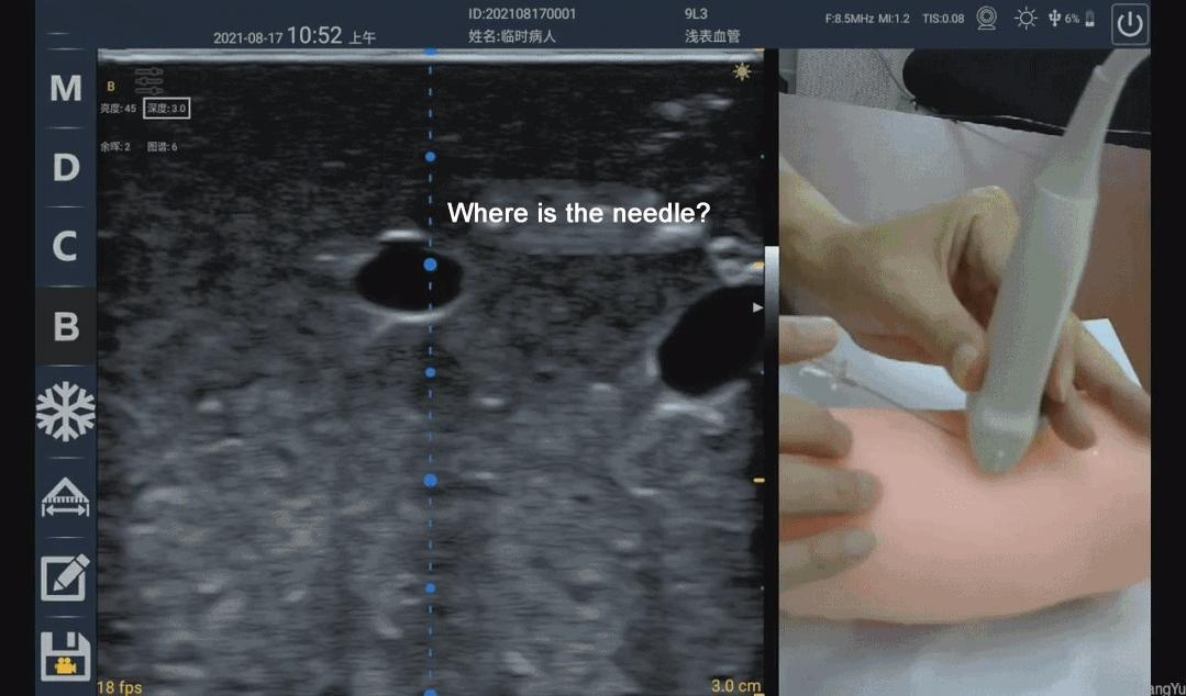
However, according to some clinical use cases observed by the author, the popularity of ultrasound equipment and the popularity of ultrasound visualization cannot be directly equated. Take ultrasound-guided puncture in the field of vascular access as an example, many people are still in a state of ignorance, which can easily lead to medical accidents. Because although there was an ultrasound, it was impossible to see where the puncture needle went. The real ultrasound-guided puncture technique first needs to ensure that the position of the needle or needle tip can be seen under the ultrasound, rather than making a rough estimate, and then "blind puncture" under the ultrasound guidance. Generally, it includes the following situations:
Ultrasound-guided puncture is generally divided into two methods: in-plane puncture and out-of-plane puncture. Both puncture techniques have applicable scenarios in the field of vascular access, and it is best to be proficient in them. (The following paragraph is an excerpt from the American Society of Ultrasound Medicine's practice guideline on ultrasound-guided vascular access surgery.)
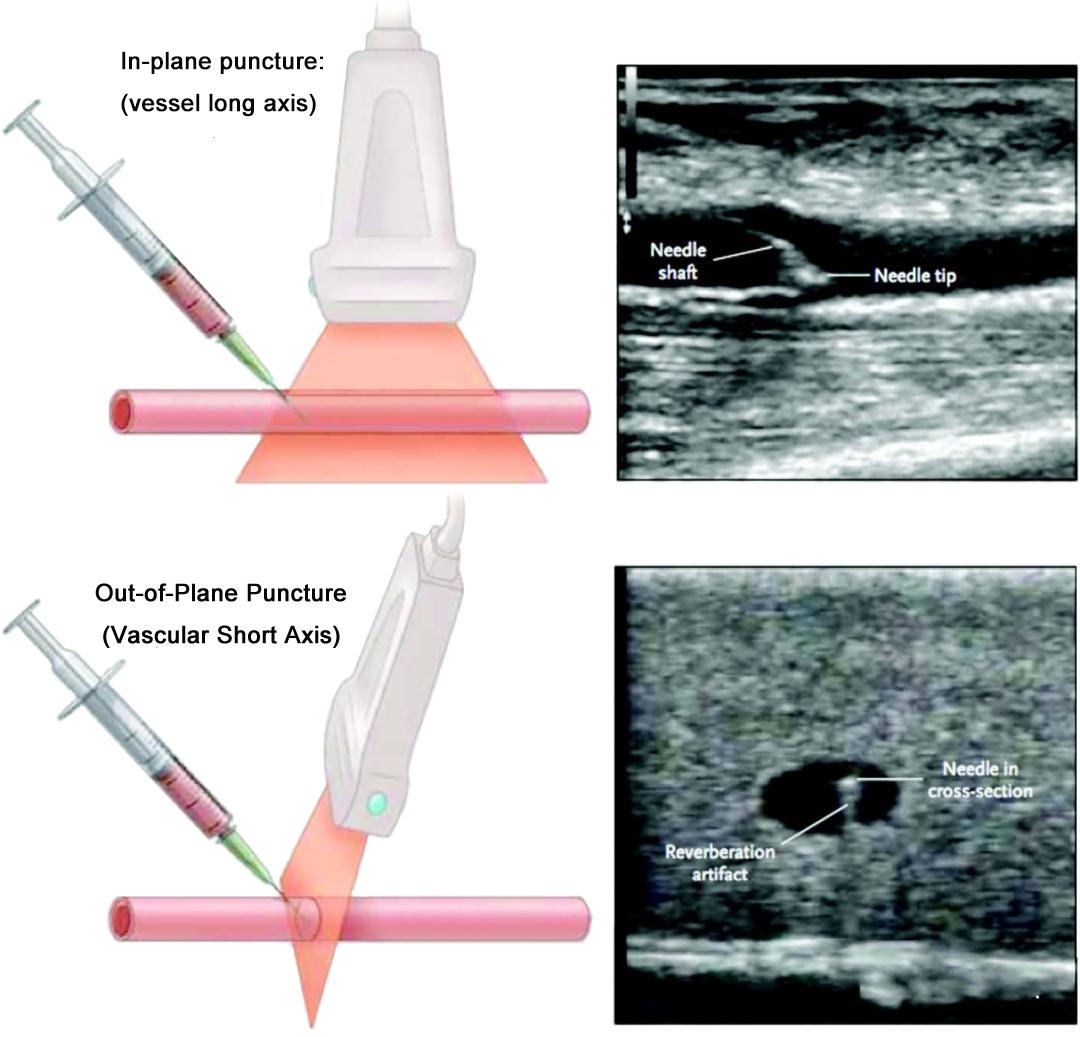
In-plane (long axis) Vs. Out-of-plane (short axis)
In-plane/out-of-plane represents the relative relationship with the needle, the needle is parallel to the ultrasound imaging plane is in-plane, and the needle is perpendicular to the ultrasound imaging plane is out-of-plane
Under normal circumstances, in-plane puncture shows the long axis or longitudinal section of the blood vessel; out-of-plane puncture shows the short axis or cross-section of the blood vessel
Therefore, vascular access ultrasound defaults to out-of-plane/short-axis, and in-plane/long-axis are synonyms
The needle can be inserted from the top of the center of the blood vessel outside the plane, but the needle tip must be tracked and positioned by rotating the probe to avoid underestimating the depth of the needle tip.
The position of the needle tip can be observed statically in the plane, but it is easy to "slip" the plane where the needle is located or/and the plane of the center of the blood vessel; in-plane puncture is more suitable for large vessels
In-plane/out-of-plane combined method: out-of-plane/short-axis scan to confirm that the needle tip puncture reaches the center of the vessel, rotate the probe to in-plane/long-axis for needle insertion
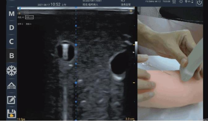
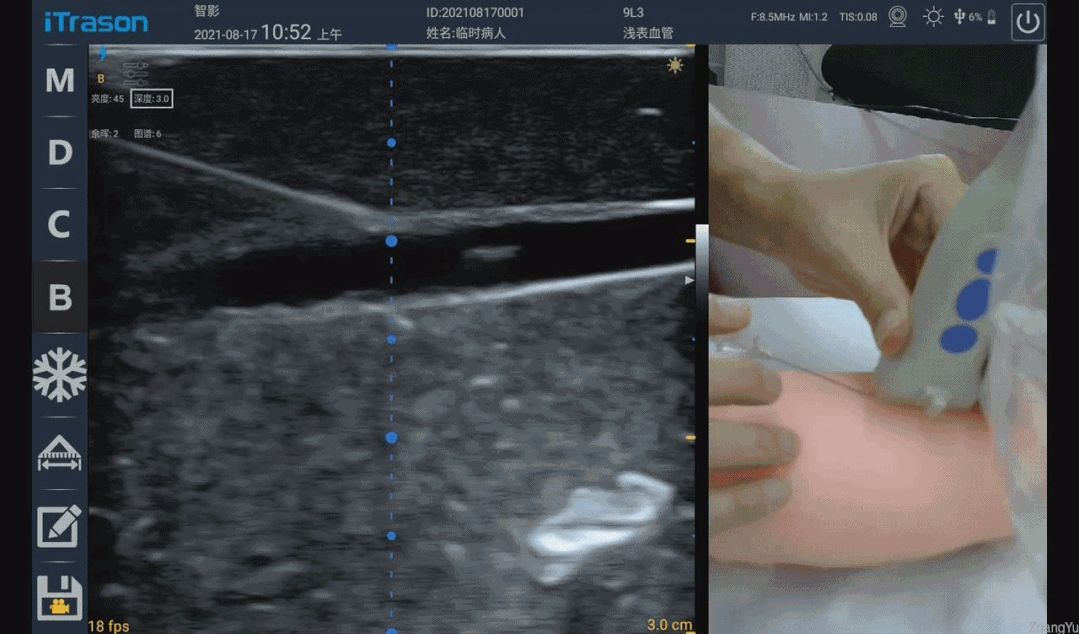
The real-time position of the needle tip or even the entire needle body can be statically observed in the plane, which is obviously very beneficial! However, without the support of auxiliary facilities such as puncture racks, it really takes hundreds of practice to keep the needle in the ultrasound imaging plane to master the skills. In many cases, because the puncture angle is too large, the puncture needle is clearly in the ultrasound imaging plane, but the needle is still invisible. Why is this?
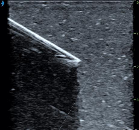
The needle insertion angles of the puncture needle in the figure below are 17° and 13° respectively. When the angle is 13°, the entire needle body of the puncture needle is very clearly displayed. When the angle is 17°, the needle body can only be vaguely seen. A little bit, and the bigger the angle is, the more you will be blinded. So why is there only a 4° angle difference, and why is there such a big difference in the performance of the puncture needle?
This also has to start with the ultrasonic emission and reception focus. Just like the aperture control in the photographic focus, each point on the photo is the combined focus effect of all the light passing through the aperture, and each point on the ultrasonic image is a The combined focusing effect of all ultrasound transducers within the transmit and receive apertures. As shown in the figure below, the range marked by the red line is the schematic range of ultrasonic transmission focusing, and the green line is the schematic range (right border) of receiving focusing. Because the needle is bright enough, specular reflection will occur, and the white line marks the normal direction of the specular reflection. Assuming that the emission focus range marked by the red line is like two "lights", after hitting the mirror surface of the needle, the reflected "lights" are like the two orange lines in the picture. Since the "light" on the right side of the green line exceeds the range of the receiving aperture and cannot be received by the probe, the "light" that can be received is shown in the orange area in the figure. It can be seen that at 17°, the probe can still receive very few ultrasonic echoes, so the corresponding image is a faint image, and at 13°, the echoes that can be received are more than 17°. The time is significantly increased, so the imaging is also clearer. As the puncture angle decreases, the needle becomes more and more "flat", and more and more reflected echoes from the needle body can be effectively received, so the needle visualization becomes better and better.
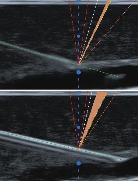
Some meticulous people will also find a phenomenon that when the angle is less than a certain value (the needle does not need to be completely "flat"), the development of the needle body basically maintains the same degree of clarity. what about this? Why is the range of transmit focus (red line) drawn smaller than the range of receive focus (green line) in the image above? This is because in the ultrasound imaging system, the emission focus can only be focused at a single depth. Although we can adjust the depth of the emission focus to make the image near the depth of our attention clearer, we don’t want the place beyond the focus depth to be very blurry. . This is very different from our need to take sugar-water photos of beautiful women. The sugar-water film requires that the background and foreground brought by a large aperture and a small depth of field are all blurred. For ultrasound imaging, we hope that the images in the range before and after the depth of focus are clear enough, so we can only use a smaller emission aperture to obtain a larger depth of field, so as to maintain the uniformity of the image. As for the receiving focusing, because the current ultrasonic imaging systems have been fully digitalized, the ultrasonic echoes of each transducer/array element can be saved, and then all the imaging depths can be dynamically processed by digital methods. Continuous focusing, so at this time, try to open the receiving aperture as much as possible, as long as the array elements that can receive the echo signal are used, so as to ensure that a finer focus and better resolution can be obtained. Back to the topic just now, when the puncture angle is small to a certain extent, the ultrasonic waves emitted by the smaller aperture can be received by the larger receiving aperture after being reflected by the needle body, so the effect of the needle body development will naturally remain basically unchanged. .
For the above probe, what should I do if the puncture needle cannot be seen after the puncture angle in the plane exceeds 17°?
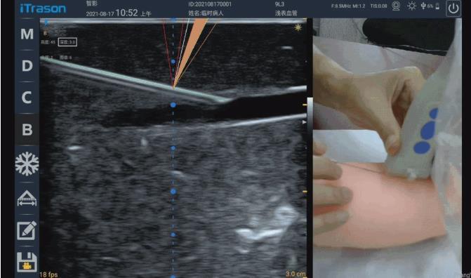
If the system supports it, you can try the puncture needle enhancement function at this time. The so-called puncture needle enhancement technology is generally to insert a frame of scanning imaging that is deflected in both transmission and reception after a normal frame of tissue is scanned. The deflection direction is the direction of the needle body, so that the reflection of the needle body can be returned The wave falls into the aperture of the receiving focus as much as possible, and the strong needle body image in the deflection imaging is extracted and displayed after being fused with the normal tissue image. Subject to the size and frequency of the probe array element, the deflection angle of the high-frequency linear array probe is generally not more than 30°, so the puncture angle exceeds 30°. It hasn't progressed to this stage yet)
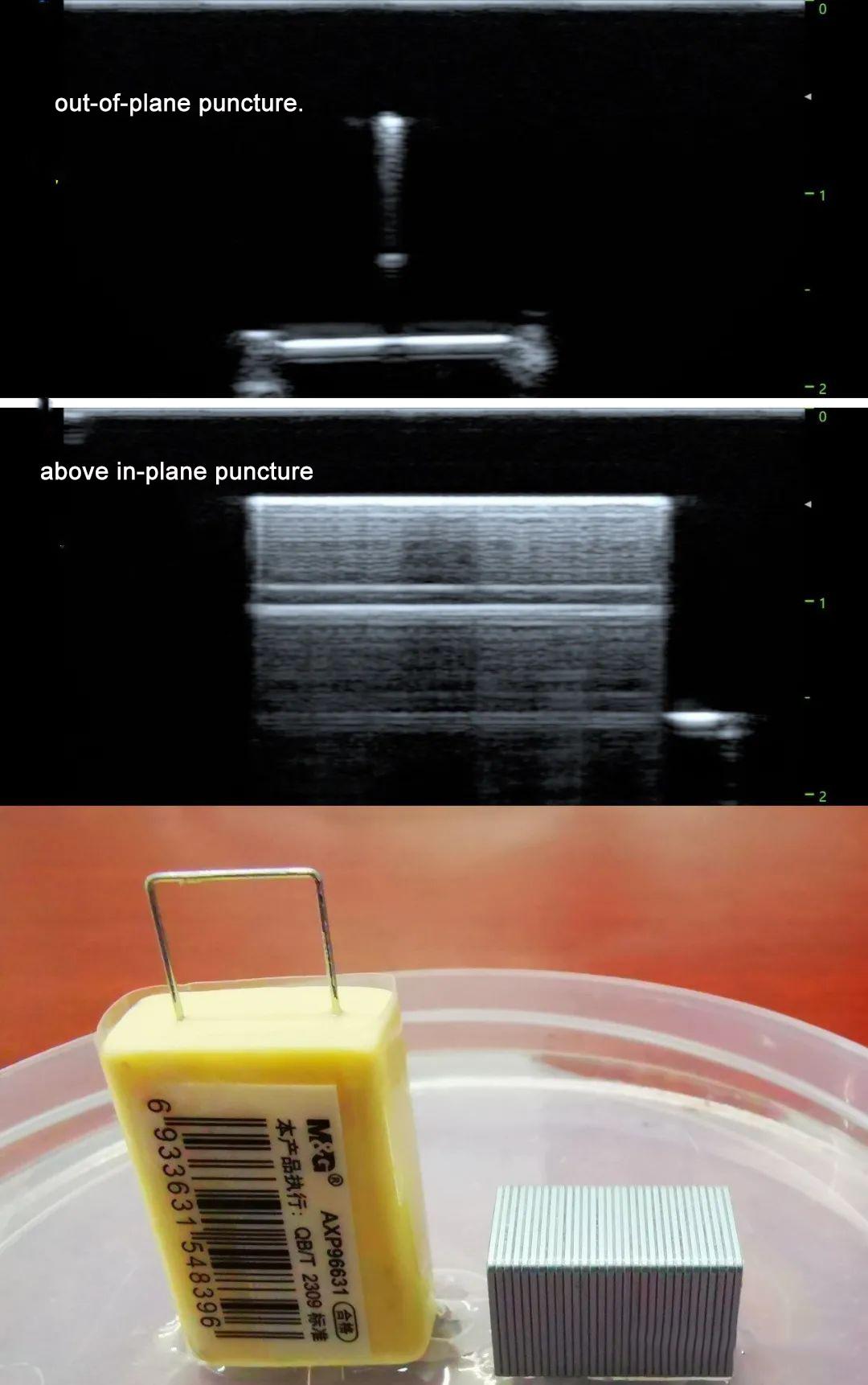
Next, let's look at the situation of out-of-plane puncture. After understanding the principle of the above in-plane puncture needle development, it will be much simpler to analyze the out-of-plane puncture needle development. The rotating fan sweep mentioned in the practice guide is a crucial step for out-of-plane puncture, which is not only applicable to finding the position of the needle tip, but also to finding the needle body. It's just that the puncture needle and the ultrasound imaging are not in the same plane at this time. Only when the puncture needle is perpendicular to the imaging plane can the ultrasonic waves incident on the puncture needle be reflected back to the ultrasonic probe. Since the thickness direction of the probe is generally through the physical focusing of the acoustic lens, the apertures for both transmitting and receiving are the same for this direction, and the size of the aperture is the width of the transducer wafer. The width of the array probe is only about 3.5mm (the receiving aperture for in-plane imaging is generally more than 15mm, which is much larger than the width of the wafer). Therefore, if the reflected echo of the puncture needle outside the plane is to return to the probe, it is only necessary to ensure that the puncture needle and the The angle between the imaging planes is close to 90 degrees. So how do you judge the vertical angle? The most intuitive phenomenon is the long "comet tail" dragging behind the strong bright spot. This is because when ultrasonic waves are incident on the puncture needle vertically, in addition to the echoes directly reflected back to the probe by the needle surface, a small amount of ultrasonic energy enters the needle. The multiple reflections back and forth, and the multiple reflection echoes that are reflected to the direction of the probe again, come later, so a long "comet tail" is formed. Once the needle is not perpendicular to the imaging plane, the sound waves reflected back and forth will be reflected in other directions and cannot return to the probe, so the "comet tail" cannot be seen. The phenomenon of the comet tail can be seen not only in out-of-plane puncture, but also in in-plane puncture. When the puncture needle is nearly parallel to the probe surface, rows of horizontal lines can be seen. Comet tail".
In order to more vividly illustrate the in-plane and out-of-plane "comet tail", we take the performance of out-of-plane and in-plane scans with staples in the water, and the results are shown in the figure below.
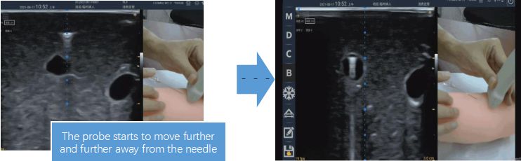
The figure below shows the image performance of different angles when the needle body is out of plane and the rotating fan is scanned. When the probe is perpendicular to the puncture needle, it means that the puncture needle is perpendicular to the ultrasound imaging plane, so you can see the obvious "comet tail" span
Keep the probe perpendicular to the puncture needle and move it along the needle body toward the needle tip. When the "comet tail" disappears, it means that the scanning section is close to the needle tip, and the bright spot will disappear further forward. The position before the bright spot disappears is where the needle tip is. Location. If you are not at ease, do a small-angle rotating fan sweep near this position to confirm again.
Welcome to contact us for more professional medical products and knowledge
contact details
Joy yu
Amain Technology Co.,Ltd.
Mob/Whatsapp:008619113207991
E-mail:amain006@amaintech.com
Linkedin:008619113207991
Tel.:00862863918480
Company official website:https://www.amainmed.com/
Alibaba website:https://amaintech.en.alibaba.com
Ultrasound website:http://www.amaintech.com/magiq_m
Post time: Aug-17-2022


